Completed 10/8/2011
Right when we moved into our house. The first thing dad wanted to change or build was the living room. The TV in the Purple house required an Ethernet connection to run Netflix and 5.1 surround sound wired for audio and dad began drawing up a design.
Design

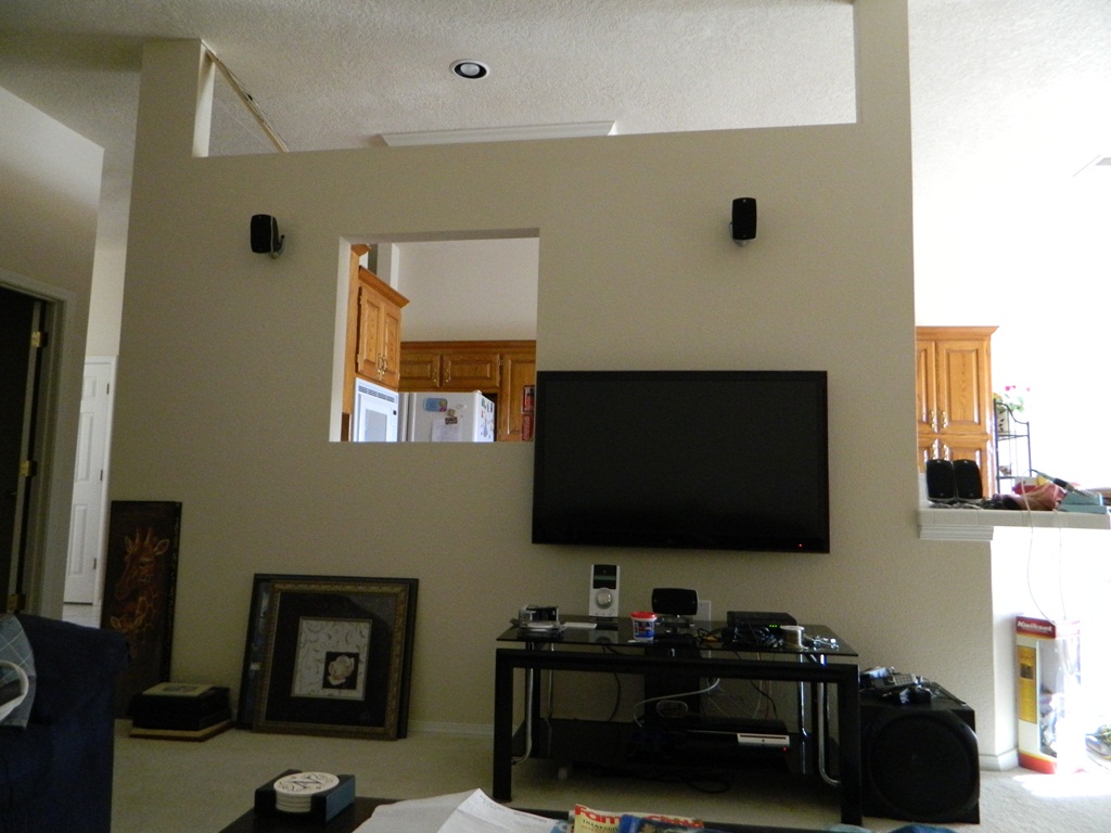
The design was based around the wall that separates the kitchen from the living room. The wall has a window allowing the person using the sink in the kitchen to look into the living room. Also, the wall was not built to the ceiling. There is a 2×2 grid of wall plates which housed, 1st quadrant – in-house intercom, 2nd quadrant – surround sound wiring, 3rd quadrant – coax cable, and 4th quadrant – 120V power.
The original design was to put the TV mounted on the wall. Hook ups would be concealed in the wall down to the four wall boxes below. Everything will be covered up behind the entertainment table. In or on the table will be the htpc, ps3, surround sound appliance, and the cable modem. Internet will be directed back into the wall up to the top gap, where the home’s wireless router is situated. Behind the router, Ethernet is piped back down to all electronics capable. The TV antenna will just sit on top of the wall.
Implementation
The TV mount is mounted on the same stud that the four wall boxes are mounted too. To retain the same standards, data will run on the same cavity as the cable and surround sound wires and power will run on the same side as the power outlet. To feed cables from the bottom to the appropriate plates in the wall, I used a Klein 25′ x 1/4″ steel fish tape to first route the cable route from one box to the next. I then electrical tape the cables to the tape and pull it back through.
Note:Stagger the bundle of cables by each a foot to prevent snagging.
Note:Electrical tape any plugs so that it’s streamlined and won’t break if snagged.
Note:If you are feeding through a old wall box, be sure to accommodate the aggregate thickness for all cables that will go through it.

The two cutouts are directly behind the tv for concealment. For the data side, I used a low voltage 1-gang metal bracket. I was able to also see the phone jack on the other side and thus was able to access telephone by adding a telephone loop off the kitchen phone jack. I used 12/3 electrical wiring (yellow) to wire up the tv and router from the original box and when building out these outlets, I did some research on which orientation I should make the outlet, I will now talk about what I’ve found.
| Vertical Outlet, Ground Pin down | Residential have been using this orientation since any electrician can remember. If the plug is partially unplugged, the weight of the plug/cable will pull the plug down and thus the ground pin is last to be unplugged. Also, usual wall warts and 90 degree plugs are produced/engineered with the ground pin down. |
| Vertical Outlet, Ground Pin up | Industrial metal plates had a hazard where if the plate became loose and falls, the two blades would short out. Installing outlets ground up allowed the plate to bounce off the ground pin and lower the chance of short/arc. |
| Horizontal Outlet, Ground Pin left | If the outlet is horizontal, It should be always oriented with the Ground Pin on the left. The wide blade (neutral) would be on top in case of anything metallic falling from above. |
Because I didn’t want to get into the debate of up vs. down, I decided to build all my future outlets sideways.
Near the top of the partial wall, I built two more cutouts. This is where the TV antenna will reside and the cabling for the wireless router. Again, I mounted the outlets horizontal with the ground pin left.
